6.5 - Nitrogen Pressure Testing
Module: Safety Leak Detection Shipping and Safe Disposal
Technical and safety verification date: August 10, 2026
Primary verification basis: Current EPA Section 608 test topics, current 40 CFR Part 82 Subpart F, current EPA service-practice guidance, and current manufacturer service manuals
Course role: Explains safe use of dry nitrogen for refrigeration-system pressure testing, including the regulator, downstream relief protection, manifold and valve configuration, equipment pressure limits, purging, test observation, and safe pressure release
Learning Objectives
After completing this section, a student should be able to:
- Explain why dry nitrogen is used for refrigeration-system pressure testing and leak checking.
- Explain why oxygen and compressed air must not be used as substitutes for dry nitrogen.
- Identify the function of the nitrogen-cylinder valve, pressure regulator, regulator gauges, downstream relief valve, manifold gauge set, hoses, and appliance service connections.
- Explain why a nitrogen cylinder must never be connected directly to a refrigeration system without pressure regulation.
- Explain why the manufacturer’s specified test pressure and the weakest component rating control the maximum allowable test pressure.
- Describe a safe generic sequence for connecting, pressurizing, isolating, observing, and depressurizing a system.
- Explain how valve configuration changes when testing an entire refrigerant circuit versus an isolated component or section.
- Explain why nitrogen pressure should be introduced slowly and in controlled stages.
- Explain why a pressure change during a standing test can be caused by temperature change as well as leakage.
- Explain how nitrogen-only pressure release differs from venting a nitrogen mixture that still contains a covered refrigerant.
- Distinguish a nitrogen pressure test from a low-flow nitrogen purge during brazing.
- Interpret the Figure 6.5.1 setup and identify unsafe configurations.
Introduction
Dry nitrogen is one of the most important service gases used in refrigeration and air-conditioning work.
It is commonly used to:
- Pressurize a refrigerant circuit for leak testing.
- Support bubble or electronic leak detection.
- Break a vacuum during a dehydration procedure.
- Sweep or purge tubing during brazing under a manufacturer-approved procedure.
- Pressurize an isolated circuit after refrigerant has been properly recovered.
EPA’s current Section 608 test-topic guidance specifically expects technicians to know:
Use nitrogen
rather than
oxygen or compressed air
for leak detection
and:
Use a pressure regulator
and relief valve
with nitrogen
The key safety reason is simple:
A nitrogen cylinder contains gas at a pressure far higher than the pressure a refrigeration system can safely withstand.
Therefore the cylinder must never be treated like a direct source connection.
A safe pressure-test arrangement must control the pressure before it reaches the refrigeration system.
The basic concept is:
Nitrogen cylinder
→ pressure regulator
→ downstream relief protection
→ manifold / service hose
→ refrigeration system
The pressure used for the test is not chosen from one universal EPA number.
Instead:
Manufacturer test-pressure instruction
+
component pressure ratings
+
applicable code / service procedure
→ allowable test pressure
This section teaches the safe general arrangement and reasoning. Detailed leak-location methods are developed in Section 6.6 - Leak Detection Methods.
Key Concepts
1. Why Dry Nitrogen Is Used
Dry nitrogen is useful because it is:
- Chemically stable under normal HVAC service conditions.
- Nonflammable.
- Free of the oxygen concentration introduced by compressed air.
- Available dry enough for refrigeration service when supplied for that purpose.
- Easy to regulate and monitor.
- Compatible with many pressure-testing procedures when the equipment manufacturer permits its use.
The word dry matters.
Moisture is undesirable inside a refrigeration system because it can contribute to:
- Corrosion.
- Acid formation.
- Ice formation at metering devices.
- Lubricant degradation.
- Evacuation difficulty.
Therefore, the service gas should not add moisture to the system being tested.
2. Why Oxygen Must Not Be Used
Oxygen is a strong oxidizer.
A refrigeration system may contain:
- Refrigeration oil.
- Residual oil film.
- Organic material.
- Refrigerant residue.
- Other combustible substances.
Introducing oxygen under pressure can greatly increase the risk of rapid combustion or explosion.
For EPA 608 preparation:
OXYGEN
→ never use as refrigerant-system pressure-test gas
This prohibition was introduced in Section 6.3 and is reinforced here because it directly affects pressure-test setup.
3. Why Compressed Air Must Not Be Used
Compressed air is not an acceptable substitute for dry nitrogen because it contains:
- Oxygen.
- Moisture.
- Potential compressor oil or other contamination.
It can also create an unsafe refrigerant-air mixture if refrigerant remains in the circuit.
Therefore:
COMPRESSED AIR
→ not an acceptable refrigerant-system leak-test gas
The safe general choice is:
DRY NITROGEN
→ with regulator
→ with relief protection
→ within equipment pressure limits
4. The Cylinder Pressure Must Be Reduced Before It Reaches the System
A nitrogen cylinder stores gas at very high pressure.
The refrigeration system may be designed for only a fraction of that pressure.
Connecting the cylinder directly to the system could:
- Rupture tubing.
- Damage coils.
- Damage valves.
- Damage pressure controls.
- Damage gauges and hoses.
- Cause a hose to whip.
- Cause serious injury.
The regulator is therefore not optional.
5. The Pressure Regulator Has Two Different Pressure Sides
A typical nitrogen regulator has:
HIGH-PRESSURE SIDE
→ connected to cylinder
and:
LOW-PRESSURE / DELIVERY SIDE
→ sends controlled pressure toward the system
Many regulators have two gauges.
A common arrangement is:
| Gauge | What It Indicates |
|---|---|
| Cylinder / inlet gauge | Approximate pressure on the high-pressure side of the regulator |
| Delivery / outlet gauge | Regulated pressure supplied toward the service hose and system |
The exact regulator configuration varies by model.
Always follow the regulator manufacturer’s instructions.
6. The Regulator Does Not Replace the Relief Valve
The regulator controls normal outlet pressure.
A downstream relief device provides another layer of protection if:
- The regulator fails.
- The regulator is adjusted incorrectly.
- Pressure rises unexpectedly downstream.
- A higher pressure becomes trapped in the service setup.
The project outline specifically requires the student to recognize a:
DOWNSTREAM RELIEF VALVE
The relief device belongs on the low-pressure side of the regulator, where it can protect the manifold, hoses, and system from excessive delivery pressure.
A useful conceptual sequence is:
Cylinder
→ regulator
→ relief valve
→ system
not:
Cylinder
→ system
→ regulator
7. The Relief Setting Must Protect the System
A relief valve is useful only if it is configured to protect the equipment downstream.
Its setting must be consistent with:
- Manufacturer test-pressure instructions.
- The rated pressure of the weakest component.
- The regulator and hose ratings.
- Applicable service procedure or code.
Do not invent one universal relief-valve setting.
The correct relationship is:
Relief protection
≤ allowable downstream test limit
subject to the actual manufacturer and device instructions.
8. There Is No Universal Nitrogen Test Pressure
Different systems require different test pressures.
Manufacturer documents can specify very different values depending on:
- Refrigerant.
- System design.
- High side versus low side.
- Component being tested.
- Type of appliance.
- Pressure-control devices.
- Test objective.
Therefore:
Do not memorize one pressure such as 100 psig, 200 psig, 450 psig, or 500 psig as a universal nitrogen test pressure.
Use the actual equipment documentation.
A manufacturer may specify one value for:
- A whole split-system line set.
and another for:
- A low-pressure component.
- A pressure switch.
- A compressor isolation test.
- A chiller circuit.
9. The Weakest Component Controls
The safe test pressure cannot exceed the rating of the weakest pressure-containing component exposed to the test.
Potential limiting components include:
- Evaporator.
- Condenser.
- Compressor shell.
- Receiver.
- Accumulator.
- Solenoid valve.
- Pressure transducer.
- Pressure switch.
- Gauge.
- Hose.
- Filter-drier.
- Heat exchanger.
- Service fitting.
The technician must know which components are connected to the test pressure.
This is one reason valve configuration matters.
Technical and Safety Details
1. Generic Nitrogen Pressure-Test Arrangement
A typical teaching arrangement is:
Dry nitrogen cylinder
        ↓
Cylinder valve
        ↓
Pressure regulator
        ↓
Downstream relief valve
        ↓
Service hose
        ↓
Manifold gauge set
        ↓
High-side and/or low-side hose
        ↓
Appliance / isolated circuit
Each component has a distinct function.
2. Nitrogen Cylinder
The cylinder is the high-pressure gas source.
During use:
- Keep the cylinder secured against falling.
- Protect the valve from physical damage.
- Use the correct regulator for nitrogen service.
- Do not move or handle the cylinder by the regulator.
- Do not use oil or grease on oxygen-service equipment; more broadly, use only compatible clean components for compressed-gas service.
- Follow cylinder, regulator, employer, and supplier safety instructions.
Detailed transportation requirements are reserved for Section 6.8.
3. Pressure Regulator
The regulator:
reduces high cylinder pressure
→ to a controlled service pressure
The technician should begin with the regulator’s delivery adjustment backed out or set according to the regulator manufacturer’s instructions before opening the cylinder.
Then:
- Open the cylinder valve according to the cylinder/regulator procedure.
- Confirm high-side pressure.
- Adjust delivery pressure gradually.
- Introduce nitrogen into the system slowly.
Do not rapidly apply full test pressure to a previously unpressurized system.
4. Downstream Relief Valve
The relief valve should be located so it protects the regulated side of the setup.
Conceptually:
Regulator outlet
→ relief valve connection
→ manifold / system
The relief path must not be:
- Plugged.
- Capped in a way that defeats protection.
- Directed toward a person.
- Located where discharge creates another hazard.
The exact relief-device installation and setpoint must follow the device and equipment manufacturer’s instructions.
5. Manifold Gauge Set
The manifold can:
- Monitor system pressure.
- Provide controlled access to the high side.
- Provide controlled access to the low side.
- Connect the nitrogen source through the service/center connection.
A common manifold arrangement is:
BLUE
→ low side
RED
→ high side
YELLOW / CENTER
→ service connection
For a nitrogen test, the service hose may connect the regulated nitrogen source to the manifold center port.
However, digital manifolds and manufacturer-specific service tools can differ.
Follow the actual tool instructions.
6. Valve Configuration Is Test-Specific
Do not memorize:
always open both manifold valves
or:
always pressurize only the high side
The correct valve arrangement depends on what is being tested.
Testing an Entire Circuit
If the manufacturer requires the full circuit to be pressurized, the service configuration must allow nitrogen to reach all intended sections.
Some systems may require:
- Both high- and low-side service connections.
- Specific service-valve positions.
- Opening or commanding solenoid valves.
- Special procedures for electronic expansion valves.
- Isolation of pressure-sensitive devices.
Testing an Isolated Section
If only one section is being tested:
isolate that section
→ keep unrelated portions protected
→ pressurize only the intended volume
A technician must understand the system flow path before opening valves.
7. Metering Devices and Check Valves Can Block Pressure Equalization
An expansion valve, check valve, solenoid valve, or other flow-control device may prevent nitrogen introduced at one connection from reaching another part of the circuit.
Therefore:
A pressure reading at one service port does not prove that every part of the system is at the same pressure.
Manufacturer instructions may require additional connections or valve positioning.
8. Introduce Pressure Slowly
A safe generic sequence is:
Start at low pressure
→ confirm setup is stable
→ inspect for obvious leaks or problems
→ raise pressure in controlled steps
→ stop at manufacturer-specified test pressure
Benefits of staged pressurization include:
- Easier detection of incorrect connections.
- Lower consequence if a fitting is loose.
- Reduced stress on components.
- More controlled regulator operation.
- Opportunity to stop before reaching an unsafe condition.
9. Close the Nitrogen Supply During a Standing Test
Once the specified test pressure is reached:
Close nitrogen supply
→ isolate the system from the cylinder
→ record pressure
→ observe
The system should not remain continuously connected to an actively supplying cylinder during the observation period unless the manufacturer procedure specifically requires it.
If the regulator remained connected and continued feeding nitrogen, it could:
- Mask a leak.
- Change the observed pressure.
- Increase pressure unexpectedly.
10. Pressure Drop Can Indicate a Leak
If:
- System volume is fixed.
- No nitrogen is added or removed.
- Temperature is stable.
then a significant pressure decrease can indicate gas loss.
However, pressure observation alone usually does not locate the leak.
Leak-location methods are covered in Section 6.6.
11. Temperature Change Can Mimic a Pressure Change
Gas pressure varies with absolute temperature.
For a fixed amount of gas in an approximately fixed volume:
where:
- = absolute pressure.
- = absolute temperature.
Therefore:
System cools
→ pressure may fall
even without a leak
and:
System warms
→ pressure may rise
even without added gas
This is why a standing pressure test should consider:
- Ambient temperature.
- Equipment temperature.
- Sun exposure.
- Warm indoor versus cool outdoor conditions.
- Test duration.
A pressure change is evidence that must be interpreted, not automatic proof of leakage.
12. Use Absolute Quantities for Gas-Law Reasoning
The gas-law relationship requires:
absolute pressure
+
absolute temperature
not:
psig
+
°F directly
For basic interpretation:
psia
=
psig
+
local atmospheric pressure
and temperature must be converted to an absolute scale such as:
- Rankine.
- Kelvin.
Detailed gas-law calculations are beyond what is normally needed for EPA 608 examination preparation, but the physical reasoning is useful.
Why Oxygen and Compressed Air Are Prohibited
Oxygen
Oxygen
→ strong oxidizer
→ can react violently with oil / combustible material
→ severe fire or explosion hazard
Compressed Air
Compressed air
→ contains oxygen
+
contains moisture
+
may contain contamination
→ unsafe substitute for dry nitrogen
Correct Exam Relationship
Leak-test pressurization
→ use nitrogen
not oxygen
not compressed air
EPA also expects:
nitrogen
→ pressure regulator
+
relief valve
Pressure-Test Workflow
Step 1 — Identify the System
Before applying pressure:
- Identify the refrigerant.
- Identify the appliance.
- Determine whether refrigerant remains.
- Identify the intended test section.
- Obtain the manufacturer pressure-test procedure.
- Identify the specified test pressure.
- Identify components that must be isolated or protected.
Step 2 — Recover Refrigerant as Required
A normal service pressure test should not be used as a way to avoid refrigerant recovery requirements.
If a covered refrigerant remains in the system, follow the applicable Section 608 recovery requirements before opening or servicing the appliance.
Current 40 CFR §82.154 exempts nitrogen itself from the Section 608 venting prohibition, but that does not authorize intentionally releasing a covered refrigerant merely because nitrogen was added to it.
Step 3 — Inspect Test Equipment
Check:
- Nitrogen cylinder condition.
- Regulator compatibility.
- Regulator condition.
- Relief valve.
- Manifold.
- Gauges.
- Hoses.
- Fittings.
- Service ports.
- Pressure ratings.
Do not use a hose, manifold, regulator, or fitting whose pressure rating is below the required test pressure.
Step 4 — Connect With Valves Closed
A general preparation condition is:
Cylinder valve
→ closed
Regulator delivery pressure
→ backed out / minimum according to regulator instructions
Manifold valves
→ closed
Then make the required connections.
Step 5 — Configure the System Valves
Set:
- Service valves.
- Solenoid valves.
- Expansion-valve state.
- Isolation valves.
- Manifold valves.
according to the manufacturer’s test procedure.
The goal is to expose only the intended components to the planned test pressure.
Step 6 — Purge the Nitrogen Service Line
The hose between the regulator and manifold may initially contain air.
A manufacturer-approved procedure may call for briefly flowing nitrogen through the service line before introducing it into the refrigeration system.
The purpose is:
remove ordinary air from service hose
→ avoid adding oxygen / moisture from hose
This is different from purging a refrigerant-containing system to atmosphere.
Step 7 — Apply Nitrogen Slowly
Open the nitrogen source according to the regulator procedure.
Then:
raise pressure gradually
→ monitor delivery gauge
→ monitor system gauge
→ inspect setup
Stop immediately if:
- Pressure rises unexpectedly fast.
- A hose moves or bulges.
- A fitting leaks severely.
- A component distorts.
- A gauge behaves abnormally.
- The relief valve opens unexpectedly.
Step 8 — Stop at the Specified Pressure
Never exceed:
- Manufacturer test pressure.
- Component rating.
- Hose/manifold rating.
- Applicable code limit.
Do not increase pressure merely because no leak has yet been found.
Step 9 — Isolate the Nitrogen Supply
Once at test pressure:
close cylinder / supply
→ isolate test volume
→ record pressure and temperature
Step 10 — Leak Check
Use the appropriate method, for example:
- Bubble solution.
- Electronic detector when compatible with the procedure.
- Pressure observation.
- Ultrasonic method where appropriate.
Section 6.6 develops these methods.
Step 11 — Repair and Retest
If a leak is found:
depressurize safely
→ repair
→ reconfigure
→ repressurize
→ retest
Do not braze a component that remains pressurized.
Step 12 — Release Test Pressure Safely
After the test:
- Close the nitrogen cylinder.
- Isolate the regulator as required.
- Confirm the pressure source is shut off.
- Depressurize the tested system or section according to the procedure.
- Direct discharged nitrogen to a safe, ventilated location.
- Do not discharge toward people.
- Verify pressure is at the required safe level before opening the circuit.
- Continue with evacuation/dehydration before charging.
Nitrogen and the Section 608 Venting Rule
1. Nitrogen Itself Is Exempt
Current 40 CFR §82.154 lists:
Nitrogen in any application
among the substitutes exempt from the Section 608 venting prohibition and Subpart F requirements.
This means a nitrogen-only pressure test does not create the same refrigerant-emission issue as intentionally venting a covered refrigerant.
2. Nitrogen Does Not Cancel Refrigerant Requirements
Do not reason:
Add nitrogen to refrigerant
→ mixture becomes exempt
That is not a valid way to bypass refrigerant recovery requirements.
The project rule remains:
Properly recover the covered refrigerant when required before conducting service work and before intentionally releasing the test gas.
3. Low-Pressure Appliance Exception Reminder
Current EPA service-practice guidance contains a specific limitation for certain low-pressure non-major repairs.
Where the rule requires a low-pressure appliance to be brought to no higher than 0 psig before opening, a method that requires subsequent purging—such as nitrogen—generally cannot be used for refrigerants boiling at or below 85°F at standard atmospheric pressure, except the specific R-113 provision described in the current rule.
This is a service-practice exception context, not the general nitrogen pressure-test rule.
Detailed Type III low-pressure procedures are reserved for Module 9.
Nitrogen Pressure Testing Versus Nitrogen Purging During Brazing
These two procedures use the same gas for different purposes.
Pressure Test
Purpose:
detect leakage / verify pressure integrity

Condition:
system or test section held at controlled positive pressure

Key controls:
regulator
relief protection
manufacturer test-pressure limit
Brazing Purge
Purpose:
reduce internal oxidation while brazing

Condition:
very low continuous nitrogen flow through tubing
not a sealed high-pressure test
Do not confuse:
pressure-test pressure
with:
brazing purge flow
A tubing circuit being purged during brazing should not be sealed and pressurized as though it were undergoing a standing pressure test.
Use the manufacturer’s brazing procedure.
Valve-Configuration Examples
Example 1 — Whole-Circuit Test
A manufacturer requires the entire field-installed refrigerant circuit to be pressure tested.
The technician may need:
regulated nitrogen
→ manifold center hose
→ high side and low side connections
with valve positions that allow nitrogen to reach both portions of the system.
The exact service valves and electronic valves must follow the manufacturer procedure.
Example 2 — Isolated Evaporator Section
Only an evaporator section is being tested.
The technician may isolate:
- Compressor.
- Condenser.
- Receiver.
- Other components not intended for the test.
Then the nitrogen pressure is applied only to the evaporator section.
The test pressure must not exceed that section’s allowable limit.
Example 3 — Pressure-Sensitive Component
A pressure switch or transducer has a lower test limit than other parts of the system.
The technician must:
- Follow the manufacturer’s test procedure.
- Protect or isolate the component if instructed.
- Use the correct test pressure.
Do not expose it to a higher pressure simply because the tubing can tolerate that pressure.
High-Pressure Nitrogen Safety
1. Stored Energy
Compressed gas contains stored energy.
A failed fitting or hose can release that energy rapidly.
Possible consequences include:
- Hose whip.
- Flying fittings.
- Sudden noise.
- Eye injury.
- Skin injury.
- Component rupture.
This is why pressure regulation and controlled pressurization are critical.
2. Use Rated Equipment
All downstream components must be rated for the pressure they will experience.
Check:
- Regulator.
- Relief valve.
- Manifold.
- Gauge.
- Hose.
- Coupler.
- Adapter.
- Service port.
- System component.
The pressure rating of the strongest component does not protect the weakest component.
3. Never Defeat Protective Devices
Do not:
- Plug a required relief outlet.
- Bypass the regulator.
- Hold a relief valve closed.
- Use an unregulated cylinder.
- Exceed manufacturer test pressure to “find the leak faster.”
4. Stand Clear of Potential Failure Paths
During pressurization:
- Keep face and body away from fittings.
- Avoid standing directly in front of a regulator outlet.
- Keep hoses controlled.
- Use appropriate PPE.
- Keep bystanders clear.
Important Terms
Dry Nitrogen
Nitrogen gas suitable for refrigeration service with sufficiently low moisture content for the intended procedure.
Pressure Regulator
A device that reduces high cylinder pressure to a controlled downstream delivery pressure.
Cylinder-Pressure Gauge
A regulator gauge that indicates pressure on the cylinder/high-pressure side.
Delivery-Pressure Gauge
A regulator gauge that indicates controlled pressure on the downstream side.
Downstream Relief Valve
A pressure-relief device placed on the regulated side of the nitrogen setup to protect downstream hoses, tools, and equipment from excessive pressure.
Test Pressure
The pressure specified for a particular pressure-test procedure.
The correct value comes from the equipment manufacturer, component ratings, and applicable requirements—not from one universal EPA value.
Pressure Rating
The maximum pressure a component is designed, listed, or approved to withstand under specified conditions.
Standing Pressure Test
A test in which a system or isolated section is pressurized, isolated from the gas source, and observed for pressure behavior over time.
Nitrogen Purge
A controlled low-flow use of nitrogen to sweep a line or tubing, such as during a manufacturer-approved brazing procedure.
It is not the same as a pressure test.
Figures and Diagrams
Figure 6.5.1
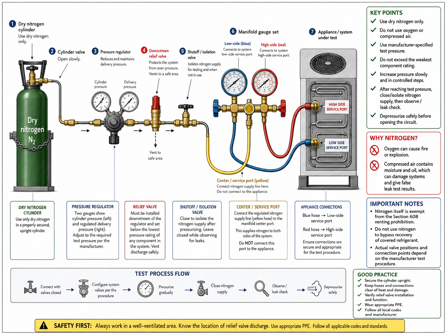
Figure 6.5.1 – Safe nitrogen pressure-test arrangement with regulated pressure and downstream overpressure protection.
AI-generated instructional figure: It may contain visual inaccuracies. Use the accompanying lesson text and cited authoritative sources to verify technical and regulatory details.
EPA 608 Exam Focus
EPA’s current Core test-topic guidance explicitly includes:
Use of nitrogen
rather than oxygen or compressed air
for leak detection
and:
Use of pressure regulator
and relief valve
with nitrogen
High-Priority Relationships
Dry nitrogen
→ acceptable general pressure-test gas
Oxygen
→ never use
Compressed air
→ never use
Nitrogen cylinder
→ regulator required
Regulated line
→ relief protection required
Test pressure
→ manufacturer specific
Common Exam Traps
A question may ask which setup is safest.
Correct reasoning should include:
- Dry nitrogen.
- Regulator.
- Relief valve.
- Pressure gauge.
- System rating.
- Controlled valve configuration.
A distractor may offer:
oxygen because it is dry
or:
compressed air because it is mostly nitrogen
Both are incorrect.
Another distractor may provide a very high nitrogen pressure and ask whether the technician can use it because the cylinder and regulator are rated for that pressure.
The answer is still controlled by:
the refrigeration system
and
its weakest exposed component
not by the nitrogen cylinder’s capability.
Common Mistakes and Confusing Points
Mistake 1: Connecting Nitrogen Directly to the System
The cylinder can contain pressure far above the system rating.
Always use the correct pressure regulator.
Mistake 2: Assuming the Regulator Alone Is Enough
EPA test topics specifically pair:
pressure regulator
+
relief valve
The relief valve provides backup downstream protection.
Mistake 3: Putting the Relief Valve on the Wrong Side
For the system to be protected from excessive regulator delivery pressure, the relief protection must be on the regulated/downstream side.
Mistake 4: Memorizing One Universal Test Pressure
Different equipment manufacturers specify different pressure-test values.
Use the current equipment procedure.
Mistake 5: Using the High-Side Design Pressure for Every Component
The weakest component exposed to the test controls.
Mistake 6: Opening Every Valve Automatically
Valve configuration depends on the circuit and what is being tested.
Mistake 7: Pressurizing Too Quickly
Rapid pressurization increases the consequences of:
- Loose fittings.
- Wrong connections.
- Regulator misadjustment.
Increase pressure gradually.
Mistake 8: Leaving the Cylinder Feeding During the Standing Test
A continuously feeding regulator can mask leakage.
Isolate the nitrogen source once the test pressure is established.
Mistake 9: Treating Every Pressure Drop as a Leak
Cooling of the gas can reduce pressure.
Interpret pressure together with temperature and leak-location evidence.
Mistake 10: Using Compressed Air Because It Is Convenient
Compressed air contains oxygen and moisture.
It is not an acceptable substitute for dry nitrogen.
Mistake 11: Venting Refrigerant Because Nitrogen Was Added
Nitrogen’s regulatory exemption does not provide permission to bypass refrigerant-recovery requirements.
Mistake 12: Confusing Nitrogen Pressure Testing With Brazing Purge
A brazing purge is a low-flow process.
A pressure test intentionally holds the system at controlled positive pressure.
Concept-Check Questions
Question 6.5-1
Why must a nitrogen cylinder not be connected directly to a refrigeration system?
A. Nitrogen always freezes refrigeration oil.
B. Cylinder pressure can greatly exceed the safe pressure of the refrigeration system.
C. Nitrogen cannot pass through a service hose.
D. A manifold cannot measure nitrogen pressure.
Question 6.5-2
Which arrangement best represents a safe generic nitrogen pressure-test setup?
A. Nitrogen cylinder → refrigeration system → pressure regulator
B. Compressed-air line → manifold → appliance
C. Nitrogen cylinder → pressure regulator → downstream relief protection → manifold → appliance
D. Oxygen cylinder → manifold → appliance
Question 6.5-3
What determines the proper nitrogen pressure-test pressure?
A. One universal EPA pressure value
B. The pressure printed on the nitrogen cylinder only
C. The manufacturer test procedure, applicable requirements, and the ratings of the components exposed to the test
D. The highest pressure the regulator can produce
Question 6.5-4
Why should the nitrogen source generally be isolated after the target standing-test pressure is reached?
A. To make nitrogen flammable
B. To prevent a continuing gas supply from masking leakage or changing the test pressure
C. To convert gauge pressure to absolute pressure
D. To remove moisture from the nitrogen cylinder
Question 6.5-5
A system pressure decreases during a nitrogen standing test while outdoor temperature also decreases substantially. What is the best interpretation?
A. The pressure decrease proves a leak.
B. Temperature change can contribute to the pressure change, so the result must be interpreted with temperature and other leak evidence.
C. Cooling always increases gas pressure.
D. Nitrogen pressure is independent of temperature.
Question 6.5-6
Which statement about manifold valve configuration is most accurate?
A. Both valves must always be fully open during every nitrogen test.
B. Only the high-side valve may ever be used.
C. Valve configuration depends on the system, the section being tested, and the manufacturer procedure.
D. Valve position does not matter because nitrogen passes through all closed valves.
Question 6.5-7
Why is compressed air not an acceptable substitute for dry nitrogen?
A. It contains oxygen and moisture and can create additional contamination and fire/explosion concerns.
B. It contains no pressure.
C. It cannot be measured with a gauge.
D. It is chemically identical to refrigerant.
Question 6.5-8
Which statement correctly describes a nitrogen brazing purge compared with a nitrogen pressure test?
A. They are exactly the same procedure.
B. A brazing purge uses low continuous flow to reduce oxidation, while a pressure test holds the system at a controlled test pressure.
C. A brazing purge requires oxygen instead of nitrogen.
D. A pressure test must always be performed with the tubing open to atmosphere.
Section Summary
The basic safe nitrogen pressure-test arrangement is:
Dry nitrogen cylinder
→ pressure regulator
→ downstream relief valve
→ manifold / service hose
→ intended refrigeration-system section
The most important concepts are:
- Use dry nitrogen, not oxygen or compressed air.
- Never connect a high-pressure nitrogen cylinder directly to a refrigeration system.
- A regulator controls normal delivery pressure.
- A downstream relief valve provides backup overpressure protection.
- The relief protection belongs on the regulated side where it can protect the system.
- There is no universal nitrogen test pressure.
- Use the manufacturer-specified pressure and protect the weakest exposed component.
- Configure service and manifold valves according to the actual system and test objective.
- Introduce nitrogen slowly.
- Close/isolate the nitrogen supply before a standing-pressure observation.
- Pressure changes can result from temperature changes as well as leaks.
- Nitrogen itself is exempt from the Section 608 venting prohibition, but adding nitrogen does not authorize bypassing refrigerant recovery.
- Pressure testing and low-flow brazing purging are different procedures.
- After testing, depressurize safely before opening or repairing the circuit.
- Evacuate/dehydrate the system after pressure testing and before final charging as required.
The next section compares the methods used to locate and evaluate refrigerant leaks.
See Section 6.6 - Leak Detection Methods.
References
Current EPA and Regulatory Sources
-
U.S. Environmental Protection Agency, Test Topics — Section 608 Technician Certification, current Core safety topics including use of nitrogen rather than oxygen or compressed air for leak detection and use of a pressure regulator and relief valve with nitrogen. Accessed August 10, 2026.
-
Electronic Code of Federal Regulations, 40 CFR § 82.154 — Prohibitions, current venting prohibition and exemption listing nitrogen in any application. Accessed August 10, 2026.
-
U.S. Environmental Protection Agency, Stationary Refrigeration Service Practice Requirements, current service-practice requirements and limitations involving nitrogen in specific low-pressure appliance service situations. Accessed August 10, 2026.
Current Manufacturer and Technical Sources
-
Daikin, Service and Troubleshooting Manual, current service guidance specifying dry nitrogen for refrigeration-system leak testing and demonstrating that actual test pressure is equipment-specific. Accessed August 10, 2026.
-
Daikin, Service Instructions, leak-testing guidance using dry nitrogen and bubble solution. Accessed August 10, 2026.
-
Carrier Transicold, current service documentation, examples of dry-nitrogen use with manifold/service valves and model-specific pressure-test procedures. Accessed August 10, 2026.
-
Trane, Installation, Operation, and Maintenance documentation, manufacturer examples showing dry nitrogen pressure testing, pressure-regulator use, explicit oxygen prohibition, and equipment-specific pressure limits. Accessed August 10, 2026.